Automatic Capsule Filling Machine NJP Series Operation Instruction
1 Replace filling tools
To change the size of capsule, replace corresponding upper and lower die assemblies, capsule feeding plate, horizontal fork, vertical fork, straightener, filling rod and dosing disk.
1.1 Replace filling die assembly
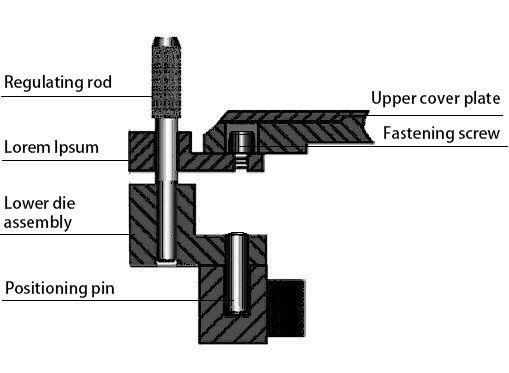
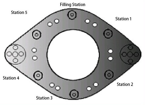
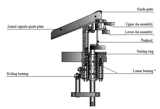
Loosen the fastening screws of upper cover plate of revolving platform and remove the upper cover plate, loosen and remove fastening screws on the upper and lower die assemblies and take out the two die assemblies. Then install the lower die assembly of another specification; align two positioning holes with two column pins of T-type axle and tighten screws. Then install the upper die assembly; insert the regulating rod of each pair of upper and lower die assemblies in the two holes at the outside respectively at Station 8 to regulate their concentricity; then tighten the screws. Make sure the regulating rod rotates freely in the holes of upper and lower die assemblies.
Caution: Move the arbor wheel of the main motor with hand shrank in replacing the die assembly and rotate the revolving platform. Remove the regulating rod before rotating!
1.2 Replace capsule-feeding unit
1.2.1 Disassembly
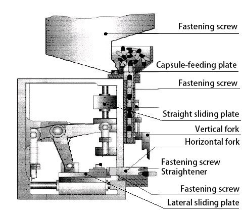
1.2.1.1 Loosen two fastening screws on capsule hopper, remove the screws and the hopper;
1.2.1.2 Move arbor wheel of main motor with hand crank and let capsule-feeding plate go to the highest position;
1.2.1.3 Loosen four fastening screws on capsule-feeding plate, remove the capsule-feeding plate;
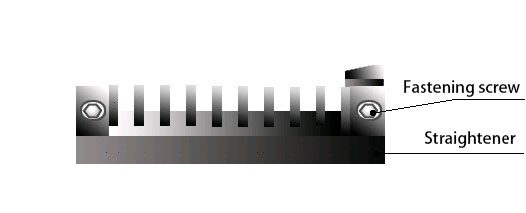
1.2.1.4 Loosen two fastening screws on straightener, remove the straightener;
1.2.1.5 Loosen fastening screws on horizontal fork, remove the horizontal fork;
1.2.2 Replacement and Installation
1.2.2.1 Align two positioning holes of straightener with the pins of casing, and tighten the screw;
1.2.2.2 Align two grooves of horizontal fork with the pin of lateral sliding plate and install on the sliding plate; adjust to feeding capsule to the optimum position and tighten screw (generally feed the body of capsule to the outer end surface of straightener);
1.2.2.3 Align two positioning holes of capsule-feeding plate and rear plate with the pin of straight sliding plate, and tighten screw;
1.2.2.4 Install capsule hopper and tighten screw (make sure the clearance around square groove and capsule-feeding plate should be uniform);
1.2.2.5 After replacing capsule feeding parts, put some empty capsules in the hopper and start vacuum pump, open capsule release unit, rotate the machine with hand crank to ensure normal capsule splitting.
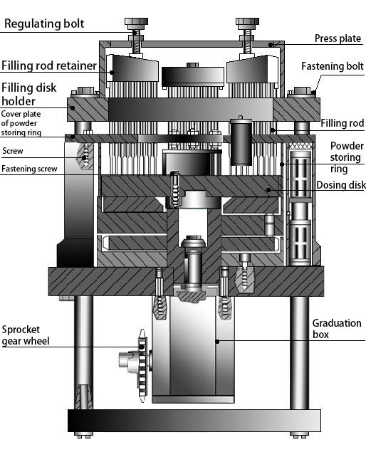
1.3 Replace dosing disk and filling rod
1.3.1 Loosen fastening screws and raise powder hopper by the resilience of spring;
1.3.2 Absorb residual power in power-store ring with dust collector;
1.3.3 Rotate the arbor wheel of main motor with hand crank until the holder of filling assembly reaches the highest position;
1.3.4 Loosen and remove acorn nut, rotate knob clockwise to uplift and remove press plate and filling retainer;
1.3.5 Loosen the screws on the small press plate with square hole under the retainer and remove the filling rod. After replacing the filling rod, replace the small press plate and fasten the screw;
1.3.6 Draw out baffle upwards, loosen two screws on both sides of powder-storing ring cover and remove baffle outside powder-storing ring, loosen four fastening screws of power-storing ring and remove the ring and cover plate from dosing disk gently from the side without removing filling rod holder;
1.3.7 Loosen three fastening screws of dosing disk with special wrench, remove dosing disk and powder-storing ring.
1.3.8 Clean the powder in the tray and replace alternate dosing disk of another specification. Do not tighten three fastening screws for the time being;
1.3.9 Insert two dosing disk regulating rods separately into multiple holes of filling rod holder at different positions. Gently rotate dosing disk so as to insert the regulating rod easily, carefully tighten three screws in turn. Should the regulating rod be unable to insert in dosing disk hole easily, you must re-adjust until the rod can be inserted easily;
1.3.10 Insert powder-storing ring and cover plate to the precise position from the side, rotate the machine with hand crank and fasten four screws of powder-storing ring. If newly-replaced dosing disk is thicker than the former one, lift the powder wiper correspondingly.
1.3.11 Fasten screws of cover plate. Carefully examine the clearance (0.05~0.1mm) between powder wiper and dosing disk with feeler gauge, then tighten fastening screws;
1.3.12 Install filling rod and retainer in their original positions and tighten acorn nut.
1.4 Adjustment after replacing die assembly
Whenever having replaced die assembly, make proper adjustment of the machine. First rotate arbor wheel of motor for 1~2 rotations with hand shrank. If anything abnormal happens, stop the rotation immediately and eliminate the trouble.
2 Adjustment of the Filling Machine
2.1 Adjustment of the exit of capsule hopper
The capsule baffle installed on the hopper can control the height of capsule at the exit by loosening the fastening knob and pulling the baffle. According to the experience, the height of exit should be preferably the half of capsule height at exit.
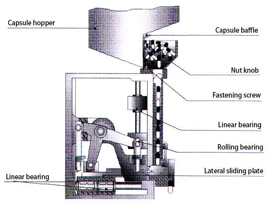
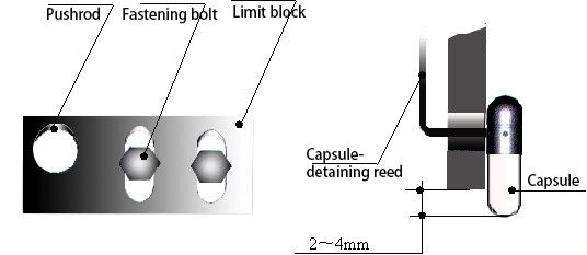
2.2 Adjustment of Capsule-Detaining Reed
The time of opening and closing capsule-detaining reed ensures that only single capsule should be discharged out of capsule-feeding plate each time. To adjust the time, loosen the fastening bolt of limit block and move the limit block to allow only single capsule to be discharged each time. Then detain the capsule to be discharged at the position as illustrated below:
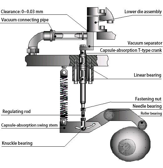
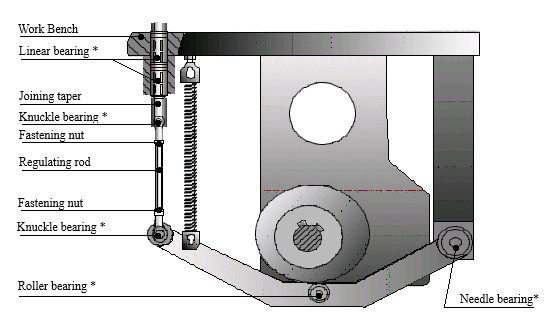
2.3 Adjustment of Vacuum Separator
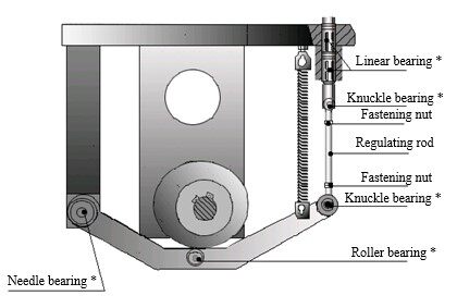
Whenever the machine runs by a station, vacuum separator goes upwards and downwards once. The position of vacuum separator is well regulated at factory’s delivery; no adjustment is needed in most common case. Should any adjustment is needed, rotate arbor wheel of main motor with hand crank until the vacuum separator reaches the highest position, loosen fastening nuts (left and right thread) on both sides of regulating rod under machine bench, rotate regulating rod to adjust vacuum separator height (clearance between upper surface of separator and the lower surface of lower die assembly), and then fasten the nuts. Recheck for several times until proper status is met. Place empty capsules in the capsule-feeding unit and start vacuum pump, rotate machine with hand crank to verify normal capsule splitting.
2.4 Alignment of upper and lower die assembly
After replacing die assembly or finding the frequent occurrence of unsplit or joined caps and bodies, make sure the alignment of die assembly is adjusted as illustrated in 5.1.1.
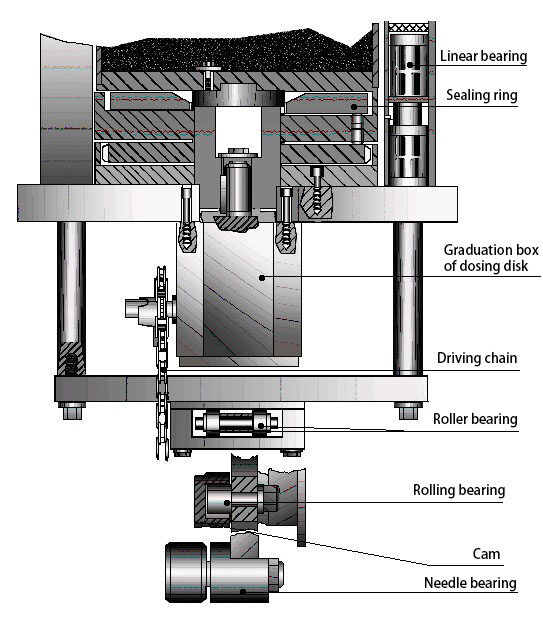
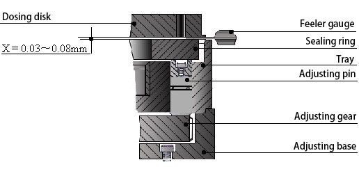
2.5 Adjustment of the clearance between dosing disk and sealing ring
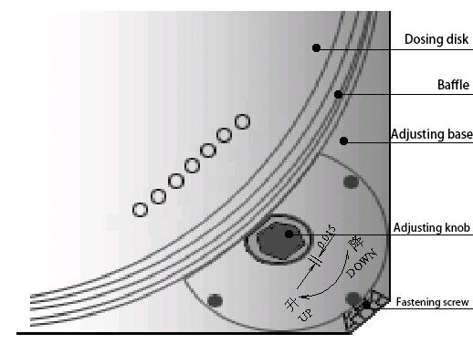
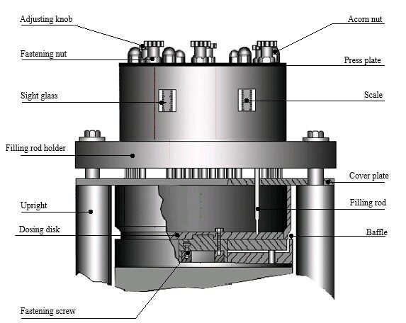
The clearance between dosing disk and sealing ring should be preferably 0.03~0.08 mm. With larger particles, the clearance may be adjusted wider. Too narrow clearance may increase the resistance between dosing disk and sealing ring. Should too much powder leakage or resistance occur in the operation, adjustment of the clearance shall be made. To adjust the clearance, draw out baffle and loosen fastening screw on adjusting base, first rotate adjusting knob counterclockwise to lower sealing ring, then rotate adjusting knob clockwise to raise sealing ring. After deciding the clearance between sealing ring and dosing disk with feeler gauge, lock the fastening screw. If sealing ring is adjusted too high, just rotate the adjusting knob counterclockwise to lower sealing ring and then rotate clockwise to raise it. Adjust from high to low shall not be allowed. The knob has a scale. Whenever you rotate one degree, sealing ring will rise by 0.015mm. After adjusting the clearance between dosing disk and sealing ring, install baffle on the tray.
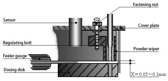
2.6 Adjustment of powder wiper clearance
Adjust the clearance after replacing dosing disk each time. The clearance should be preferably 0.05~0.1 mm. To adjust the clearance, loosen the fastening nut and rotate adjusting screw to raise or lower the powder wiper. Measure the clearance with feeler gauge and tighten the fastening nut.
2.7 Adjustment of the height of filling rod retainer
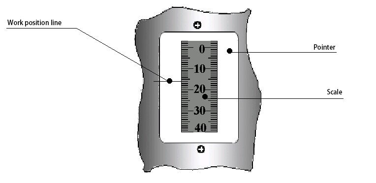
The density and volume of powder column change with the height of the filling rod. Appropriate adjustment of filling rod height leads to precise volume of powder filling. The depth that filling rod enters dosing disk may be decided upon the reference table and not be too deep. When filling rod disk holder is at the lowest position, the “0” scale line of retainer represents that the lower surface of filling rod is at the same level as the lower surface of dosing disk, i.e., the numerical reading aligned with the work position line of sight glass is the very height of the lower end surface of filling rod from sealing ring. To adjust the height, loosen the fastening screw on adjusting rod, rotate the knob on the screw stem counterclockwise so as to raise the filling rod, and then rotate the knob clockwise to lower it to desired height, finally tighten the fastening nut. That is to say, adjustment shall be made in the order from high to low. (When the thickness of dosing disk is 18mm)
|
Station |
1 |
2 |
3 |
4 |
5 |
|
Depth into dosing disk |
9 |
5 |
3 |
2 |
0.5 |
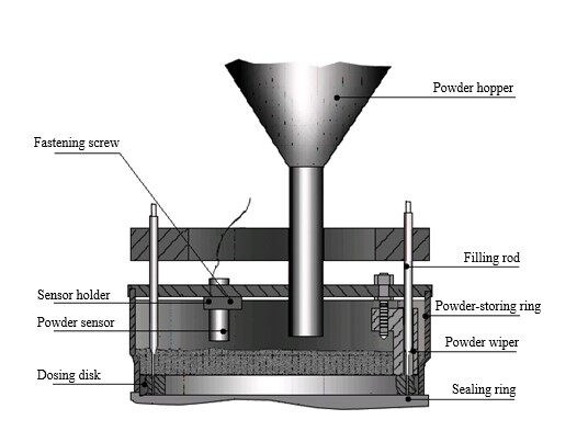
2.8 Adjustment of powder height sensor
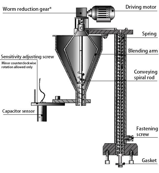
Capacitor sensor is applied to control the height of powder in the powder-storing ring. The signal emitted by sensor controls the start and stop of feeding motor. Therefore, the height of sensor decides the height of powder in powder tank. Appropriately adjust the height of sensor according to powder specification and its flowability to obtain precise filling volume. To adjust the height of sensor, loosen the screw on the sensor and raise or lower the sensor. After adjustment, fasten the screw. The screw in the upper part of sensor may control sensitivity. The distance between sensor and powder is 2~8mm.
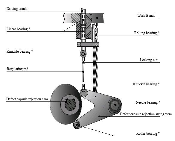
2.9 Adjustment of defect capsule rejection
At station 6, the pushrod reciprocating vertically can reject unseparated capsules in the upper die assembly. By adjusting the bolt on the cam connecting rod, the pushrod reciprocating vertically can avoid bump with the upper and lower die assembly and simultaneously reject the Defect Capsules. The column pin after the adjustment should be in the center of die assembly hole. The clearance between the guider on the Defect Capsule box and the die assembly can be adjusted by adjusting the fastening screw to such a position that the die assembly will not bump into the capsule while the capsules may be smoothly led out.

To adjust regulating rod height, loosen fastening screws on knuckle bearings on both ends of regulating rod, rotate regulating rod to adjust pushrod height. Put unsplit capsule in the hole of upper die assembly at Station 6, move main motor shaft with hand crank to raise and lower the regulating rod, see to it that defect capsules are successfully absorbed, finally tighten nut. The adjustment of pushrod must be careful to avoid collision between upper and lower die assemblies when pushrod runs vertically.
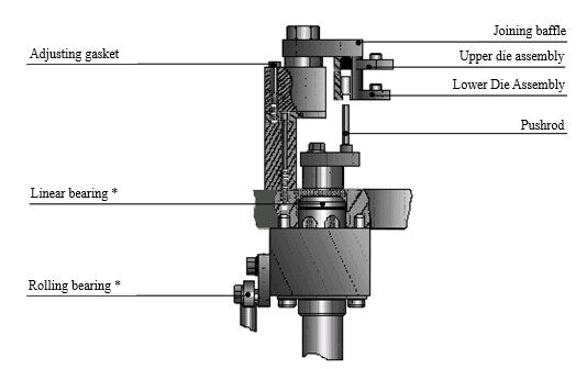
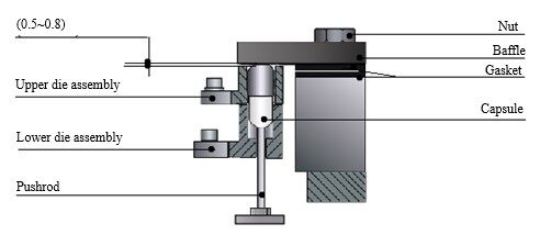
2.10 Adjustment of capsule joining
Adjustment of length of capsule joined shall be made according to the different sizes and lengths or when replacing capsule. The clearance between joining baffle and the capsule in the die assembly should be preferably 0.5~0.8 mm. The clearance can be adjusted by replacing the gaskets of different thickness. To adjust the height of pushrod, place the joined capsule in the die assembly, adjust the length of bolt on the joining tapper to such a position that when the pushrod is at the highest position, the column pin can just contact the lower part of capsule. If joining capsule seems not normal in the course of filling, e.g., the capsule is too long to join or too short to maintain regular shape, re-adjustment shall be made carefully. After the adjustment, fasten the nut.
2.11 Adjustment of leading-out unit for finished product
Adjustment of lead-out unit for finished product consists of joined capsule guide plate and pushrod adjustment. Joined capsule guide plate has guide grooves with the same distance as die assembly holes. Loosen fastening nut on guide plate on both sides; adjust the angle and height of guide plate so that guide grooves can align with the joined capsule that is driven out. The standard is to lead out joined capsules smoothly. Finally fasten the nut.
The method of adjusting joined capsule crown rod is the same as adjusting joining crown rod. As illustrated in Fig and explained in Section 5.2.10, you may adjust pushrod to decide pushrod height so as to eject capsules when pushrod arrives at the highest position. When pushrod arrives at the lowest position, the upper surface shall be lower than the lower surface of lower die assembly.
2.12 Adjustment of Overload Clutch
Overload clutch is a device installed in the output end of main motor reductor. Overload clutch can protect the machine in case of overload. Overload clutch should not slip under normal load. Since slippery may occur in long-term operation, the round nut of overload clutch should be tightened to guarantee both the normal operation and protective function.
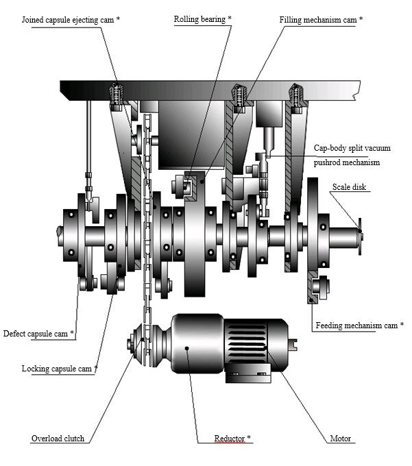
2.13 Adjustment of driving cam
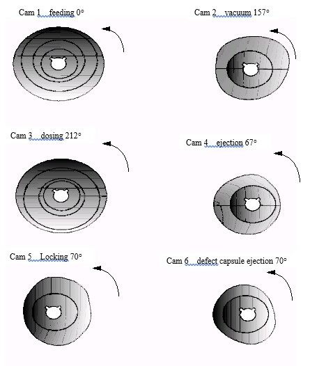
The positions of driving cam are regulated at factory before the delivery. Do not adjust these positions in normal condition. Should adjustment be made, carefully adjust in accordance with the angle given by the Fig.
Front View of Scale Disk
When cam position is as illustrated in the following figures, the indicating angle of scale disk of main arbor is as follows:
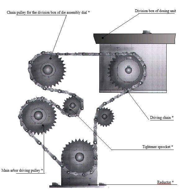
2.14 Adjustment of driving chain
If you find the chain is too loose, you can adjust the chain by moving jockey pulley but neither let the chain go off any chain pulley nor unlock the chain, otherwise the movement order of the whole mechanism will be disturbed.
Check the chain once a week. Tighten and lubricate the chain if necessary.
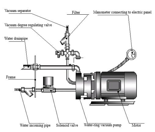
2.15 Adjustment of Vacuum
Clean water is used in water-ring vacuum pump with a low water flow. Vacuum degree can be controlled with a shutoff valve connecting to a vacuum gauge. Generally, -0.02~-0.06 MPa is advisable to guarantee the split of capsule without damage. With too high vacuum degree, open vacuum regulating valve to a larger extent. With too low vacuum degree, close vacuum regulating valve to a less extent or turn it off.
More capsule filling machine information to browse our online store.
Leave your comment
Also Offers


Containment Automatic Capsule Filling Machine SFK-703

Fully Automatic Dosator Capsule Filling Machine CZ-40


Our Team
As an expert in the pharmaceutical and pharmaceutical packaging industry, iPharMachine has provided solutions for hundreds of pharmaceutical and health product manufacturers for 17 years. By visiting customers, we get good reviews from our customers.
- info@ipharmachine.com
- English Español Deutsche