Pneumatic Vacuum Conveyor QVC series: Debugging and Installation
Fix the vacuum hopper of the pneumatic vacuum conveyor onto the hopper of sheet press or packing machine (or other machines) with a ring. In case that the vacuum hopper could not be directly fixed onto the hopper of the material-receiving machine a support could be made for fixing the vacuum hopper.
The control box is hung on the vacuum hopper when the goods are delivered, it can be hung on any other proper places according to the working conditions.
Connection of pipe for compressed air.
A. Selection of diameter of pipe for entry compressed air (referring to the machine installation room):
Select 1/2″pipe for QVC-1,2,3;
Select 3/4″pipe for QVC-4,5,6;
Directly use φ10 PU pipe for QVC-1 vacuum feeder.
B. Ball valve or filter decompression valve should be installed at the position where compressed air pipe gets in the room of the machine.
C. For QVC-1, 2 vacuum feeders, connect the outlet of the filter decompression valve to the inlet connection of the compressed air at the lower side of the control box. The size of compressed air pipe should be the same as the inlet connection of the compressed air at the lower side of the control box.
D. For QVC-3, 4, 5, 6 vacuum feeders, connect the outlet of the filter decompression valve directly to the inlet connection of the vacuum generator. The size of compressed air pipe should be the same as the inlet connection of the compressed air on the vacuum generator.
E. Connect the compressed air pipe between control box and vacuum generator according to diagrams 1 and 3.
Plug AC 220V plug to power socket, the time display on the control box is on now, this means power has been connected on the system. Note power cable must be 3- line. The control cabinet needs be grounded reliably to avoid that the control chip ends up due to interference. See electrical schematics for wiring diagram for control box.
Touch key for time increase/decrease. Set the feeding time to 5—15 seconds and set discharge time to 6—12 seconds. For powder materials feeding time should be set shorter and discharge time should be set longer, while for pellet materials feeding time should be longer and discharge time should be shorter.
Press “ON/OFF” key compressed air is fed to vacuum generator, vacuum is produced in vacuum hopper and feeding is realized.
At this time you should pay attention to the pressure of the compressed air. The pressure of the supplied air should be 0.5—0.6Mpa. The pressure of the supplied air refers to the pressure of compressed air in the system when the vacuum generator works, i.e. during feeding. There is gauge on the vacuum generator for QVC-3, 4, 5, 6 and reading on the gauge should be regarded as standard. But for QVC-1, 2 there is no gauge on the vacuum generator and the gauge on the filter decompression valve should be regarded as standard. In the debugging you should pay special attention to that the pressure of supplied air 0.5—0.6Mpa refers to the air pressure in the system during feeding. During discharge or on standby the pressure displayed on the gauge on the filter decompression valve should be 0.7—0.8Mpa. Many users, when they installed feeders, often set the filter decompression valve at 0.6Mpa. If at this time vacuum generator begins to work the pressure of the system suddenly drops to 0.4Mpa, which results failed feeding or short feeding capacity. For long distance feeding or greater feeding capacity air pressure in the system must reach 0.6Mpa.

Leave your comment
Also Offers
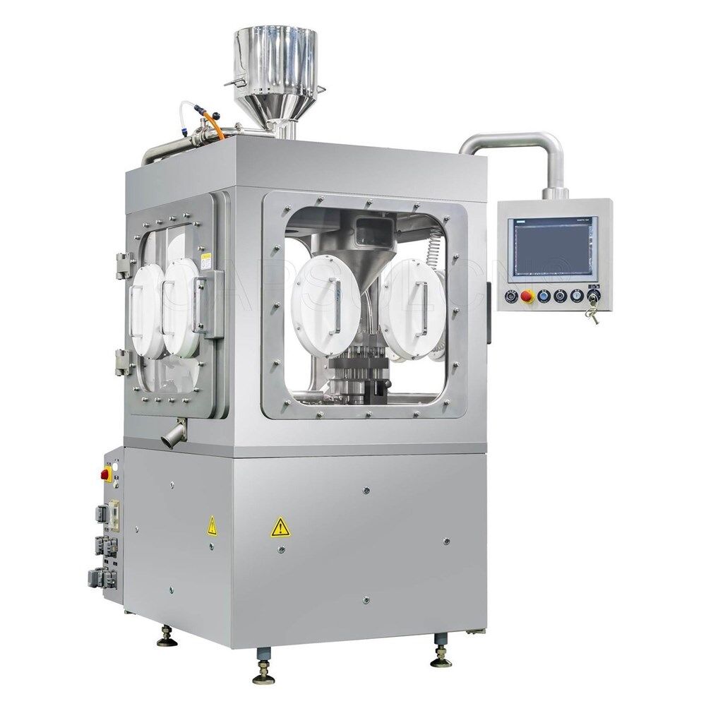
Containment Automatic Capsule Filling Machine SFK-703
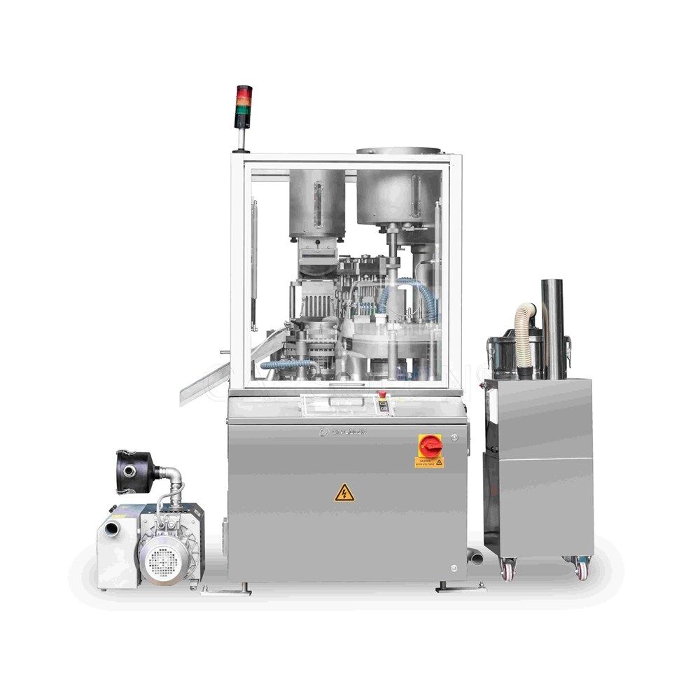
Fully Automatic Dosator Capsule Filling Machine CZ-40

Our Team
As an expert in the pharmaceutical and pharmaceutical packaging industry, iPharMachine has provided solutions for hundreds of pharmaceutical and health product manufacturers for 17 years. By visiting customers, we get good reviews from our customers.
- info@ipharmachine.com
- English Español Deutsche
